Description
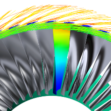
At the ITSM a generic test case was designed to investigate aeromechanical phenomena and condensation in low-pressure (LP) steam turbines. This test case, referred to as Steam turbine Test case for Aeromechanics and Condensation (STAC) consists of the two last stages of a LP steam turbine and is representative for a modern steam turbine design. STAC is intended to serve as a numerical test case to allow studying the fields of aerodynamic damping and spontanous condensation in LP steam turbine last stages.
Motivation
In the last decades, the design of LP steam turbines has been pushed to new heights given the large potential for performance improvements, as this is the part in steam turbines where most of the energy conversion takes place. Among others, the advances in materials led to blade lengths in the last stage rotors of usually over one meter. The resulting high aspect ratio of those blades in combination with high flow velocities leads to strong susceptibility to aeromechanical phenomena, in specific flutter.
Due to the rapid expansions in steam turbine last stages a non-equilibrium thermodynamic state occurs, which leads to spontaneous condensation. This is a rather unique feature in the aerothermodynamics of LP steam turbines and goes along with additional losses.
As a matter of fact, there are extremely few test cases reported in the open literature that involve relevant three-dimensional geometries. Therefore, STAC is intended to serve as a numerical test case to gain deeper knowledge in the fields of aerodynamic damping and spontanous condensation in LP steam turbine last stages.
Geometry
STAC is a two stage low pressure steam turbine, which is representative for a modern steam turbine design. The basis of the design was a geometry from the open-source tool Multall by Denton. Subsequently, the geometry was adapted with an in-house tool to widen the operating range of the machine and to meet structural requirements of the last stage rotor.
For the first stage the blade lengths at the leading edge are 0.40 m for the stator and 0.64 m for the rotor, respectively. To prevent possible blade excitation due to aerodynamic forcing the blade count of the stator is 39 and the rotor has 41 blades. The last stage stator consists of 37 blades and the rotor of 45 blades with a blade length of 1.27 m.
Wet Steam Flow
The non-equilibrium steam (NES) model of the commercial flow solver ANSYS CFX 19.1 is used at the ITSM to model wet steam flows. This model uses a so-called source specific droplet representation and is based on an Eulerian-Eulerian approach, which accounts for droplet formation and droplet growth and gives a realistic represenation of the wet steam flow.
Aeroelasticity
From the perspective of aeroelasticity the combination of high blade lengths with wet steam flow creates a special operating field for LP steam turbine rotors. Typical for axial machines the first two modes of the last stage rotor are bending modes with eigenfrequencies of 81.3 Hz and 139.5 Hz respectively. The third mode is a pure torsional mode at 175.4 Hz and the fourth mode is a combined bending and torsional mode at 249.3 Hz.
Publication
The complete description of the test case is available in
Fuhrer C., Grübel M., Vogt, D. M. (2019), A generic low-pressure steam turbine test case for aeromechanics and condensation. Proceedings of the Institution of Mechanical Engineers, Part A: Journal of Power and Energy. https://doi.org/10.1177/0957650919833207
Download
- Geometry file (.iges)
The provided .iges-file contains surfaces of all blades and a hub and shroud contour - Inlet boundary conditions (.csv)
The .csv-file contains inlet boundary conditions for the flow field at design conditions


